Building a geodesic torus
 Way back when I was an undergrad, I was a member of the Quincy
University math club, and also took a course in polyhedral geometry,
both led by Professor Vince Matsko. As
a part of one or the other of them, I put together a number of "nets"
for assembling card stock paper models of assorted polyhedra and
geodesics.
Way back when I was an undergrad, I was a member of the Quincy
University math club, and also took a course in polyhedral geometry,
both led by Professor Vince Matsko. As
a part of one or the other of them, I put together a number of "nets"
for assembling card stock paper models of assorted polyhedra and
geodesics.
Fast forward to 2005. On a visit to Quincy, Monmouth professor Lyle
Welch spotted some of the models we'd put together back then, and as it
happened, Vince still had some of the old printouts, which Lyle
photocopied and brought back to his students to assemble. On a visit to
Monmouth for a math colloquium, Knox professor Andy Leahy spotted my
name next to the model (as the "designer"), somewhat to his
surprise.
I was pretty surprised too, actually. I hadn't even looked at this
stuff in ten years. But I'd kept all my files (through two moves), and
sure enough, there was torus.ps, in the "Quincy files"
subdirectory of the "Brown files" directory on my current hard drive,
still with a last-modified date of Mar 2 1995. Lyle was
curious if it could be made to generate geodesic tori of other
frequencies.
So I set about re-learning Postscript (it's a programming language,
believe it or not, even though it's mostly used as a sort of printer
machine code). I had made some efforts at making my original file
general, but there were bugs; if you changed some of the parameters, it
wouldn't work. A bit of tweaking, and it's all fixed now.
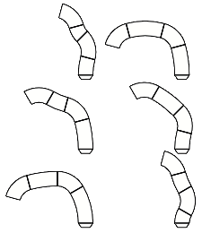
The "6x12" means that the file will print out six strips, which when cut
out, folded, and assembled form one slice making up one twelfth of a torus.
To change these numbers, just go in and edit the postscript file with
any text editor (vi, TextEdit, Notepad); skip to the bottom and change
the numbers under the heading "YOU CAN CHANGE THESE PARAMETERS"---both
the number of pieces per slice and the number of slices per torus can be
safely increased without changing the page layout (the file will
automatically make as many pages as necessary). If you want to decrease
either frequency, you may need to tweak the layout so that pieces don't
overlap or run off the page; to do that, edit the section "YOU CAN
CHANGE THIS IF YOU KNOW WHAT YOU'RE DOING", for which I may at some
point post instructions. :)
How it works
A geodesic is
the shortest path along a surface between two points; to a first
approximation, a "great-circle" path. On a sphere, these geodesics are
all pieces of circles that run through the sphere's centre, and in a
three-dimensional model you can represent the geodesic with a
sector either of that circle or of a corresponding
annulus (that
is, a ring, although "ring" means something else to algebraicists). The
points you connect with the geodesics can be any set of points that all
lie on the solid, e.g.
icosahedral
or something more complicated like a
truncated
dodecahedron, or something else.
 So, a torus.
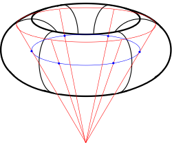
A torus is what you get when you take an arbitrary circle
and rotate it about an axis that does not intersect it. You can
"freeze" the rotation and look at just one of the component circles, and
this is one sort of "great circle" path---call it a longitude, because
it runs vertically and
all such circles are the same size within a given torus. Now restart
the rotation, but look at just one point on the rotated circle as it
rotates. The circle it traces out is another sort of "great
circle"---call it a latitude. As a point of reference, I will also
establish the term "circle-of-rotation" to refer to the circle traced
out by the centres of all the longitude circles (marked in blue in the
diagram to the right).
So, a torus.
A torus is what you get when you take an arbitrary circle
and rotate it about an axis that does not intersect it. You can
"freeze" the rotation and look at just one of the component circles, and
this is one sort of "great circle" path---call it a longitude, because
it runs vertically and
all such circles are the same size within a given torus. Now restart
the rotation, but look at just one point on the rotated circle as it
rotates. The circle it traces out is another sort of "great
circle"---call it a latitude. As a point of reference, I will also
establish the term "circle-of-rotation" to refer to the circle traced
out by the centres of all the longitude circles (marked in blue in the
diagram to the right).
Calculating the outlines of the ring sectors for the longitude circles
is fairly straightforward: they are fragments of a full-circle ring
drawn around one point on the circle-of-rotation. If each longitude is
to be divided into six parts, each ring sector will be a 60 degree
portion of the longitude circle.
The latitude circles are a bit trickier. Two of them---those that
lie in the torus plane---are essentially like the longitude rings.
But the general case? We want every
point on the strip of paper that represents a latitude
(red circle in the diagram) to be on a line connecting that
latitude with the circle-of-rotation. All such points taken
together define a frustum, with the apex of the implied cone lying on
the torus' axis of rotation.
Now for a bit of trigonometry. If you look at a cross-section of the
torus and cone, as pictured below, you have a diagram that could have
come out of basic high-school trig.
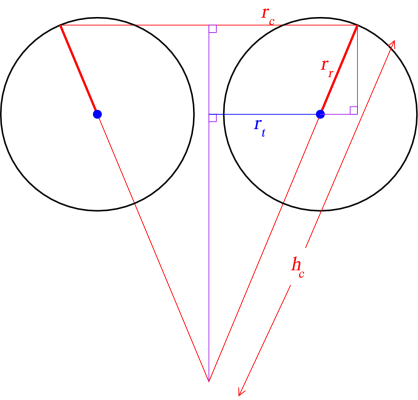 As an input to the problem, we'll be given the radius of the
circle-of-rotation (rt) and the radius of the "ring" cross-section of
the torus (rr). When we do the calculations for a given latitude
(θr), we can compute the radius of the cone as
As an input to the problem, we'll be given the radius of the
circle-of-rotation (rt) and the radius of the "ring" cross-section of
the torus (rr). When we do the calculations for a given latitude
(θr), we can compute the radius of the cone as
rc = rr cos θr + rt
The hypotenuse of the larger right triangle is the side of the cone
(hc) and can be computed as
hc = rt sec θr +
rr
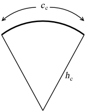 Now we need to "unroll" the cone. If we want to make a cone out of a
piece of paper, we cut out a sector of a large circle, and bring the
straight edges together. The radius of the sectored circle will be
hc,
and the entire circumference of the cone's base (cc) is then just some
fraction of the sectored circle's circumference. The sector angle
(θc) is then calculated using the equation
Now we need to "unroll" the cone. If we want to make a cone out of a
piece of paper, we cut out a sector of a large circle, and bring the
straight edges together. The radius of the sectored circle will be
hc,
and the entire circumference of the cone's base (cc) is then just some
fraction of the sectored circle's circumference. The sector angle
(θc) is then calculated using the equation
θc / 360° = 2πrc /
2πhc
or
θc / 360° = rc / hc
The actual angle we need to use will be smaller, since we do not want to
generate the entire frustum in one strip; the angle will depend on how
many "slices" we wish to make (ns) into the torus:
θs = θc / nt
So at this point, we require five parameters: the radius of the
torus; the thickness of the torus (aka the radius of the slice); the
width of the strips; the number of slices; and the number of latitudes
to take. The default torus.ps has a torus radius of 4 (1 unit is about
a half an inch), a slice radius of 2, and a strip width of 1, with 12
slices and 6 latitudes. With those dimensions, we can calculate
everything we need to. Each printed strip will have to be a "rectangle"
on the torus surface, travelling first along one latitude, then down a
longitude, then back along the next latitude, and finally up the
original longitude. Though the strip width will be the same for all of
these, the radius of the arc will vary, as will the subtended angle.
The number of unique strips is dictated by the number of latitudes, as
each strip within a slice will be distinct, but each slice is completely
identical. Thus, the file need only create the nets for one slice, and
it can let a photocopier do the rest of the work.