Designing circuits
There is a standard, cookbook algorithm to get a Boolean algebra expression for a circuit from a truth table. It is guaranteed to work, although it might be tedious and require a lot of gates. It produces what is called the canonical sum of products form, also called the disjunctive normal form. The reasons for the names will become clearer later on, but the basic idea is this: in any truth table, each row where the final result is 1 represents a distinct way to fulfill the truth conditions of the circuit. So we can build a circuit by meeting the truth conditions one way, OR a second way, OR a third way....
Consider the example of the following truth table, which represents the "implication function", sometimes written ⇒:
| A | B | ⇒ |
| 0 | 0 | 1 |
| 0 | 1 | 1 |
| 1 | 0 | 0 |
| 1 | 1 | 1 |
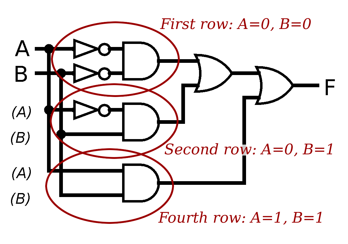
- A could be false and B could be false; or
- A could be false and B could be true; or
- A could be true and B could be true.
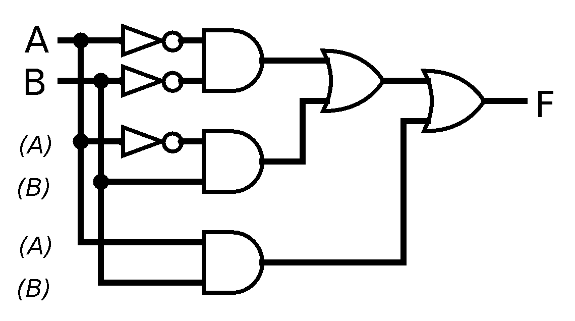
One thing worth noting about that diagram. When we draw a circuit, we only want to represent each input (here A and B) as entering the circuit once, no matter how many times their value is used in the gates of the circuit. We draw this by splitting each input so that the same "signal" can be used in multiple places. In this diagram, the places that A and B are "reused" are indicated parenthetically, but in general, diagrams of this sort won't do that---but notice that the pair of them occur in the same order each time they're used, which makes the diagram easier to follow.
Also note that when lines simply cross, there is no connection between them, they just happen to cross visually; when a dot is drawn at the intersection (usually a T-intersection to "split" an input), that indicates that the wires at that junction carry the same signal.
So, let's boil down that process into an algorithm that can work more generally to build a circuit.
- First, focus on the rows that have 1 in the result column. Ignore all other rows.
- Next, for each such row, make an expression or a sub-circuit that uses and to connect all the inputs, using the input itself if its value in the row is 1, and the not of the input if its value in the row is 0.
- Finally, use or gates to connect the outputs of all the and gates.
For the first step of the algorithm, we start with the truth table:
| A | B | ⇒ | |
| 0 | 0 | 1 | ← |
| 0 | 1 | 1 | ← |
| 1 | 0 | 0 | |
| 1 | 1 | 1 | ← |
Here's another example. Consider the function f defined by the truth table
| x | y | z | f | |
| 0 | 0 | 0 | 1 | ← |
| 0 | 0 | 1 | 0 | |
| 0 | 1 | 0 | 1 | ← |
| 0 | 1 | 1 | 1 | ← |
| 1 | 0 | 0 | 1 | ← |
| 1 | 0 | 1 | 0 | |
| 1 | 1 | 0 | 1 | ← |
| 1 | 1 | 1 | 0 |
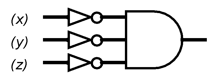
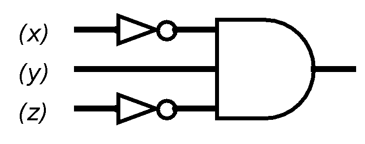
The first, third, fourth, fifth, and seventh rows have 1 in the f column, so we mark them as rows to keep track of. Ignore the other rows. In the first row, all three variables are 0, so the gate expression for the first row would be
In the third row, x is 0, y is 1, and z is 0, so the sub-circuit is
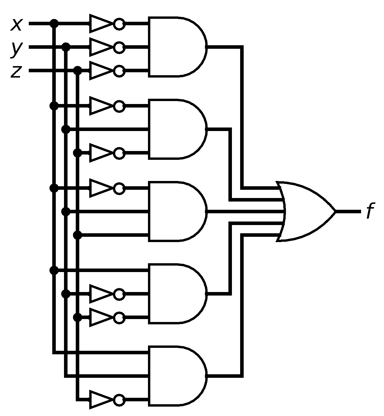
We can similarly build sub-circuits for the other three marked rows. To combine the five sub-circuits, we again use or, so that the gate expression is
or (not x and y and not z)
or (not x and y and z)
or (x and not y and not z)
or (not x and not y and z)
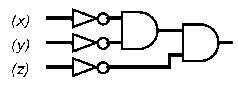
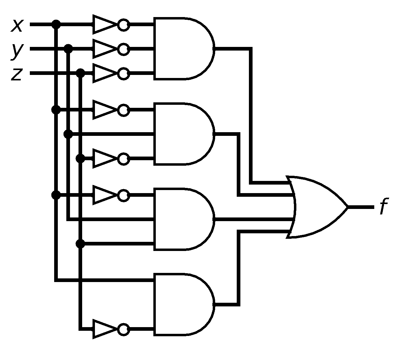
Circuits built according to this algorithm are rarely the simplest possible circuit to compute a particular function, and sometimes we can, through cleverness or trial-and-error, make changes to simplify the circuit. For instance, we could observe that in the above circuit, the bottom two and gates have the same input from x and z, but one requires y to be true and the other requires y to be false... but that's another way of saying that if x is true and z is false, we don't care what the value of y is and can, in that case, ignore y entirely. That gives us this functionally equivalent, but simpler, circuit:
Exercises
In problems 1 through 4, a function f is defined by the truth table. Construct a gate-logic expression for f using the sum-of-products algorithm, and draw the corresponding circuit.
-
x y f 0 0 1 0 1 0 1 0 0 1 1 1 -
x y f 0 0 0 0 1 1 1 0 1 1 1 1 -
x y z f 0 0 0 1 0 0 1 0 0 1 0 0 0 1 1 1 1 0 0 0 1 0 1 1 1 1 0 1 1 1 1 0 -
x y z f 0 0 0 1 0 0 1 0 0 1 0 0 0 1 1 0 1 0 0 1 1 0 1 1 1 1 0 1 1 1 1 1 - We need to
design a circuit for the majority
function, which has three inputs, and outputs 1 when a majority of its
inputs are 1.
- Build a truth table whose result column represents the majority function.
- Write the gate-logic expression corresponding to this truth table, using the sum-of-products algorithm.
- Draw the circuit corresponding to that expression.
- We are trying
to design a circuit that has three inputs and outputs 1
whenever an odd number of inputs are 1.
- Build a truth table whose result column is true when an odd number of inputs are 1.
- Write the gate-logic expression corresponding to this truth table, using the sum-of-products algorithm.
- Draw the circuit corresponding to that expression.
Credits and licensing
This article is by Robert P. Webber and Don Blaheta, licensed under a Creative Commons BY-SA 3.0 license.
Version 2015-Oct-24 23:00